What is the Internet Protocol?
Understanding the Invisible Envelope that Delivers Data Across the Globe
Before you read further, take a moment to ask yourself: What is the Internet Protocol (IP)? Can you explain its purpose & what it is consisting of beyond just “it’s how devices get IP addresses”?
Like many developers, I had a functional understanding of the stack: I knew TCP provides reliable connections, UDP is for fast messages, and IP addresses are where packets go. But when I really stopped to ask, “What is the Internet Protocol?”, I realized I was stuck.
For IP, the only thing I could picture was an IP Address. This led to a fundamental confusion: Is the Internet Protocol just a standard for addresses?
The answer, of course, is no. After digging into the architecture, I finally built a mental model that clicks. Here is what I learned.
The Protocol is Not the Address
First let’s see the well-known OSI Model:
+---------------------+
| Application Layer   |  (HTTP, FTP, DNS)
+---------------------+
| Transport Layer     |  (TCP, UDP)
+---------------------+
| Network Layer       |  (IP)
+---------------------+
| Data Link Layer     |  (Ethernet, Wi-Fi)
+---------------------+
| Physical Layer      |  (Cables, Radio Waves)
+---------------------+Why above graph only contains 5 layers instead of 7?
If you are confused why the above graph only contains 5 layers instead of the usual 7, check out my channel post. TL;DR: people often use a simplified “Internet stack” view where OSI’s Session/Presentation layers are folded into the Application layer, and Physical + Data Link are commonly treated together as “the link” (even though they’re distinct in the strict OSI model).
From this model, it’s easy to see the functionality of IP: it operates at the Network Layer, responsible for routing packets from one host to another across different networks.
The biggest mental block was separating the address name (the IP address) from the logic (the IP protocol). Once you start understanding IP as a set of rules and procedures rather than just a label, the rest falls into place.
The internet is a series of wires, IP is the logic that navigates the wires. The IP address, on the other hand, is part of the protocol (like a street address in a mailing system) but not the whole story. I gave a short talk about How Computer Networks Route Your Packets, and actually the logic of Routing is also part of the Internet Protocol. What’s more, IP also defines how packets are structured (the IP Header), how fragmentation works (note that large packets may need to be broken down; on Ethernet MTU is often 1500 bytes), and the delegation of IP addresses (CIDR, DHCP, SLAAC, etc).
The postal office analogy is one of the best mental models in networking (from my perspective). When you send a letter, the postal system functions similarly to how IP works:
- Envelope: The IP protocol defines how to package data into packets with headers containing source and destination addresses.
- Addressing: The national addressing system ensures each location has a unique identifier, just like IP addresses.
- Routing: The postal system routes letters through various post offices; similarly, IP routes packets through routers across networks.
And let’s talk about routing in more detail with the above 3 components in mind.
The IP Header
The Internet Protocol has a single focus: getting a packet from Computer A to Computer B. It is completely agnostic about what is inside that packet. It doesn’t care if it’s a fragment of a 4K video, a move in a competitive game, or a simple text file.
Let’s first see the IP Header for IPv4 (credit: UC Berkeley CS168):
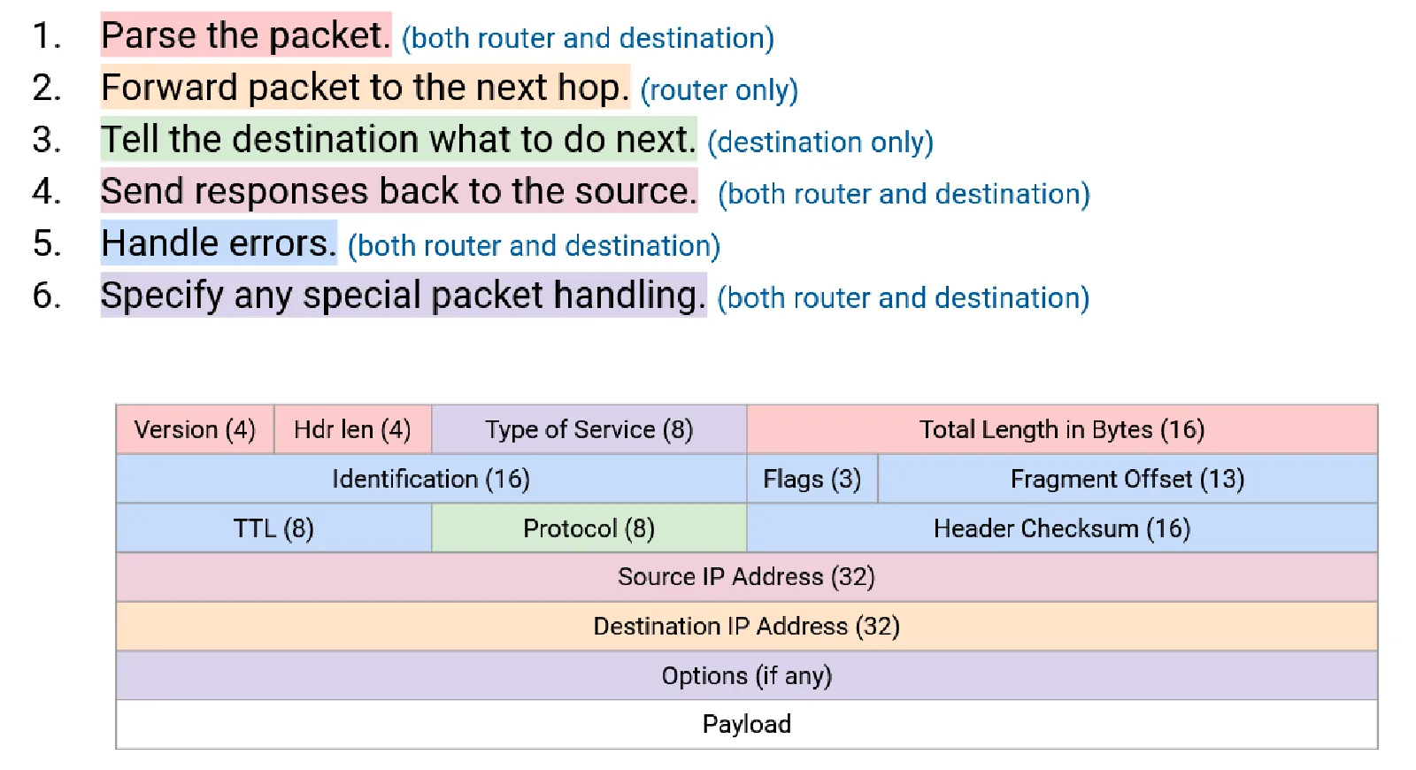
There are so many fields in the header, but when you take a closer look at it, you’ll find many of them are pretty useful. For example:
- Version: Indicates whether it’s IPv4 or IPv6.
- Source & Destination IP: The “From” and “To” addresses. We need these to know where to send the packet & where to send back the response.
- TTL (Time To Live): Prevents packets from circulating forever.
- Protocol: Indicates whether the payload is TCP, UDP, ICMP, etc. This is for demultiplexing the Layer 4 protocol at the destination. Otherwise the payload would be gibberish.
- Header Checksum: Ensures the integrity of the header data. NOTE: This checksum only covers the header, not the payload. This is due to the end-to-end principle: payload integrity is handled by the end hosts, not the routers.
- Fragmentation Fields: Allow large packets to be broken down into smaller fragments for transmission and reassembled at the destination.
The IPv6 header is simpler and more efficient (credit: UC Berkeley CS168):
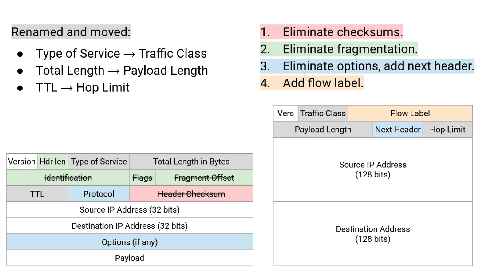
You can view it as an evolution of the IPv4 header and pushing the End-to-End Principle even further by:
- Removing the Header Checksum (relying entirely on upper-layer protocols for error checking).
- Simplifying fragmentation (only the source handles fragmentation; intermediate routers don’t fragment).
It also ensures scalability with the next header field, allowing extension headers without complicating the base header.
Addressing
Before we talk about routing, we must ask: how do devices get these addresses in the first place?
We have moved away from the rigid “Class A/B/C” system of the 1980s to Classless Inter-Domain Routing (CIDR). If you want to learn about the old-school Class A/B/C system, you could view this channel post. CIDR allows us to slice IP space at any bit boundary, creating subnets of any size to fit the need perfectly.
The CIDR notation is nothing fancy; if you are not familiar with it, here is a quick refresher:
An IP address is a 32-bit number (IPv4) or a 128-bit number (IPv6). For simplicity, we take IPv4 as example. What if we want to represent a block of addresses (e.g. 10.0.0.0 to 10.0.0.255)? We could write it as 10.0.0.*, of course, but this fails at examples such as 10.0.0.0 to 10.0.0.127. Instead, we use CIDR notation: 10.0.0.0/24 to represent the first example and 10.0.0.0/25 for the second. The /24 or /25 indicates how many bits are fixed for the network portion of the address. If you are still confused, let’s write it in binary:
10.0.0.0/24 means:
00001010.00000000.00000000.00000000
|----- 24 bits fixed -----| Hosts |

The first 24 bits define the network, fixed.
The last 8 bits are free for host addresses.
This gives us 2^8 = 256 addresses (10.0.0.0 to 10.0.0.255).
We write `/24` because 24 bits are fixed for the network.

10.0.0.0/25 means:
00001010.00000000.00000000.0|0000000
|------ 25 bits fixed ------| Hosts |

The first 25 bits define the network, fixed.
The last 7 bits are free for host addresses.
This gives us 2^7 = 128 addresses (10.0.0.0 to 10.0.0.127).
We write `/25` because 25 bits are fixed for the network.The beauty of CIDR is its flexibility. You can carve up address space at any bit boundary, creating subnets of exactly the size you need. A /30 gives you 4 addresses, while a /22 gives you addresses. This efficiency is what allows the internet to scale beyond the rigid Class A/B/C system. Similarly, for IPv6, the total bit length is 128 bits, and a very common LAN subnet size is /64.
Now the practical question: who hands out addresses to hosts? This is where DHCP and SLAAC come in, and they solve slightly different problems.
DHCP (IPv4)
In IPv4, the default model is DHCP (Dynamic Host Configuration Protocol): a server “leases” configuration to clients for a limited time.
What the client gets is usually more than just an IP:
- IPv4 address
- Subnet mask
- Default gateway
- DNS servers
- Lease time (and other options)
The handshake you’ll often see described is DORA:
- Discover: client broadcasts “is there a DHCP server?”
- Offer: server offers an address + options
- Request: client requests that offer
- Ack: server confirms (lease is now active)
Two important operational details are easy to miss:
- Leases expire and renew. Clients try to renew partway through the lease (often around 50%), and if renewal fails they can “rebind” by broadcasting to any DHCP server.
- DHCP works across subnets using relays. Broadcasts don’t cross routers, so networks commonly deploy a DHCP relay (often on the router) that forwards DHCP requests to a centralized server.
This “stateful” model is simple for admins: one place to audit, reserve static leases, and manage options.
SLAAC (IPv6)
IPv6 introduced SLAAC (Stateless Address Autoconfiguration) because the world needed to number billions of devices without a central server tracking every single assignment.
In a SLAAC environment, the router doesn’t hand out individual addresses. Instead, it periodically sends Router Advertisements (RA) (part of NDP/ICMPv6) that say:
- “Here is the prefix for this link (often
/64).” - “Here is the default gateway.”
- “Here are timing parameters (valid lifetime, preferred lifetime).”
Each host then creates its own address by combining:
- the advertised prefix
- a self-generated Interface ID (lower 64 bits)
That Interface ID is not always derived from MAC due to privacy concerns. Modern OSes commonly use temporary, randomized addresses; it rotates over time to reduce tracking. Before a host starts using the address, it runs Duplicate Address Detection (DAD) to ensure no one else on the link is already using it.
So SLAAC is “stateless” in the sense that no server maintains a lease database of host addresses. The network advertises the prefix; hosts pick their own. (It’s also common to mix SLAAC + DHCPv6: SLAAC for the address, DHCPv6 for DNS/search domains, depending on network policy.)
DHCPv6 Prefix Delegation (PD)
Here’s the missing piece that makes home IPv6 feel different from home IPv4: With IPv4, home networks often relied on NAT: your router got one public IP and hid everyone else behind it. In IPv6, NAT is discouraged, while it IS possible for you to setup NAT66 on OpenWRT or similar router, it is not the common practice (I mean, IPv6 has enough addresses, why bother?).
IPv6 aims to restore end-to-end addressing, so your home router needs not just one address, but a block large enough to carve into multiple /64 LANs (guest Wi‑Fi, IoT VLAN, etc). That’s what PD is for.
Think of it as a two-level process:
- ISP -> Router (DHCPv6-PD): your router requests a prefix using an IA_PD (Identity Association for Prefix Delegation). The ISP “delegates” something like a
/56or/60to your router. - Router -> LAN Hosts (SLAAC via RA): your router takes that delegated block, selects one
/64per LAN segment, and advertises each/64via Router Advertisements. Hosts then self-assign addresses using SLAAC.
Routing
So how does a packet find its way across the ocean? Routers make decisions based on a logic called Longest Prefix Match (LPM). A router doesn’t memorize every single IP address on earth. Instead, it memorizes “prefixes” (recall what we discussed above, the CIDR). If a packet matches multiple entries in the routing table, the router always picks the most specific one (e.g. If a /24 and /22 both match, it picks /24 routing).
But where do these tables come from? This is the domain of Routing Protocols, which are divided into two distinct families based on their scope, IGP and BGP.
IGP
Interior Gateway Protocols (IGP) operate within a single AS (Autonomous System).
What is an Autonomous System?
Remember: we view the whole Internet as a network of networks. It is not a centralized system, but rather a federated system. Within each small network we may have our own routing policies. To manage this complexity, the concept of an Autonomous System (AS) is introduced.
An Autonomous System (AS) is a collection of IP networks and routers under the control of a single organization that presents a common routing policy to the internet. Each AS is assigned a unique AS number (ASN) for identification.
There are 2 major IGP protocols:
- Distance-Vector Protocols
- Link-State Protocols
It is pretty common that you have no idea about what the above 2 protocols is about. But before I dive deeper into them, let me give you a quick summary:
- Distance-Vector Protocols get the full view of the network by getting their neighbors’ routing tables periodically.
- Link-State Protocols get the full view of the network by local computation and flooding the network with link-state advertisements.
Maybe ths above explanation is awful 😢, maybe you still don’t grasp the point. Don’t worry, hope you can grasp the details below.
Distance-Vector Protocols
Let’s first look at a picture to understand how distance-vector protocols work:
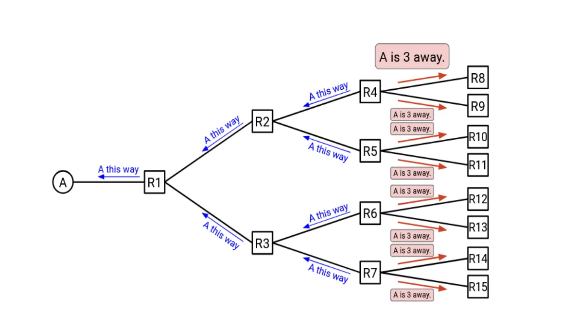
In distance-vector protocols, each router maintains a table (vector) that lists the best known distance to each destination and the next hop to reach that destination. Periodically, each router shares its table with its immediate neighbors. Formally, we can state the update process as:
- If you hear about a path to some destination, update the table if:
- You don’t have a path to that destination yet, or
- The new path is shorter than your current known path.
- Tell your neighbors about your updated table.
This process is exactly what we state above “getting their neighbors’ routing tables periodically”. Routers get How far is each destination by “neighbor’s result” + “cost to reach that neighbor”.
But as you might notice, this process has some problems. The major problem is: if a link goes down, it can take a long time for all routers to realize that the path is no longer valid and find the new optimal path.
One simple optimization to address the above problem is to add the poison packets mechanism. When a router detects that a link is down, it immediately informs its neighbors that the distance to the affected destination is infinite (or some very large number). But adding the packet would also cause some problem we haven’t seen before (what I do not want to cover here). If you want to see the final algorithm when adding the poison packets, here it is:
- If you hear an advertisement for that destination, update the table and reset the timer if:
- The destination isn’t in the table, or
- The advertised cost + link cost is better than the best-known cost, or
- The advertisement is from the current next-hop (includes poison advertisements).
- Advertise updates to neighbors when the table changes, and periodically.
- Don’t advertise back to the next-hop (split horizon), or advertise poison back (poison reverse).
- Any cost ≥ a threshold (e.g., 16 in RIP) is treated as infinity.
- If a table entry expires, mark it poison and advertise it.
Link-State Protocols
Distance-vector spreads results (“here’s my best distance”). Link-state spreads facts (“here’s what I’m directly connected to”). See the picture below:
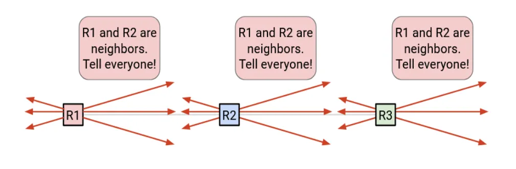
In a link-state protocol (OSPF / IS-IS), each router does three big things:
-
Discover neighbors
Routers exchange hello messages to find adjacent routers and form neighbor relationships. -
Flood link-state advertisements
Each router advertises the state and cost of its local links (e.g., “I have a link to R2 with cost 10”).
These LSAs are flooded (forwarded onward) until convergence. -
Run Dijkstra
Once everyone has the same topology database, each router independently runs Dijkstra to compute a shortest-path tree rooted at itself.
The result becomes the router’s forwarding entries (“to reach prefix X, next hop is Y”).
This approach has several advantages over distance-vector:
- Faster convergence: link-state can react to changes more quickly since routers have a full view of the topology.
- Routing Logic is consistent: all routers compute the same shortest-path tree, it is less likely to have routing loops.
However, there are tradeoffs, one major problem is it consumes More CPU/RAM: maintaining a database and running Dijkstra is heavier than basic distance-vector.
BGP
IGPs are about “best path by metric” inside one organization. BGP is about policy across organizations. Note that the network is federated: no one entity controls the whole Internet. Each AS has its own policies about which routes to accept, prefer, or advertise. Trasferring packets across AS boundaries requires it to obey these policies.
BGP (Border Gateway Protocol) is the Internet’s inter-domain routing protocol. It’s often described as a path-vector protocol:
Why not link-state?
Remember that in the link-state protocol, each router floods the network with link-state advertisements to build a complete topology map. From the privacy perspective, this is not acceptable for BGP. Each AS wants to keep its internal topology & customers private. Instead, BGP only shares reachability information (which prefixes can be reached) along with path attributes, without revealing the internal structure of the AS.
At a high level, the global Internet is many ASes (ISPs, cloud providers, enterprises, universities). Each AS can run its own IGP internally (OSPF/IS-IS/etc.). At the edges, ASes use BGP to exchange which prefixes they can reach.
For more details about peering & transit, iBGP & eBGP, hot-potato routing, please check my short talk about How Computer Networks Route Your Packets. Here I’ll just omit these details.